OVERVIEW
|
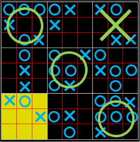
This was a team project completed in my final year of university. We chose to create an FPGA implementation of the game Ultimate Noughts and Crosses using VGA colour graphics. My role was to implement the graphics, whilst other members of the group handled the game logic and controls.
|
|
Controls and State Machine Logic
|
An overview of the control logic can be seen on the right. The user controls update the state machine logic, the state machine state is then converted to inputs for the VGA graphics which are then displayed on the screen.
To play the game, the inputs on the FPGA development board was used. A specific grid position could be selected using switches 1-9 with the confirmed position chosen using button 1. Button 4 reset the game. Inputs were checked and validated before sending to the state machine. There were 9 game states and the logic flow chart on the right explains how this works. The parser would then convert the game state machine to large arrays that show/hide the on-screen elements. |
|
VGA Logic
|
The Video Graphics Array (VGA) implementation that I created had a resolution of 640x480 pixels at 60Hz. It works by sequentially sending pixel data from left-to-right, top-to-bottom (like scan lines on a CRT screen). Timings are handled using horizontal-sync and vertical-sync pulses controlled by a clock pulse. The colour pixel data is sent via the red, green and blue analogue signals using a digital-to-analogue-converter (DAC) as the logic iterates over each screen pixel. The logic implementation of the VGA standard is summarised on the right.
I conducted lots of testing using oscilloscopes and VGA displays. |
|
