OVERVIEW
|
Hearing aids are an effective treatment but many people with hearing loss still struggle to hold conversations when in noisy environments. My project was to design an assisted listening device for those who are hard of hearing, specifically designed to improve the signal-to-noise ratio when used in noisy environments.
Simulations were conducted to evaluate various digital signal processing techniques including broadside and end-fire array beamforming, dynamic range compression, noise gates and multiband equalisers. The results from the simulations were used to make objective hardware and software design decisions for the concept device. Validation testing was done to measure the performance of the concept device and to compare it against specific aims and objectives. This was used to determine the successfulness of the project. The sections below lay out the modern digital signal processing techniques and the testing that was conducted to validate the concept proposed. |

|
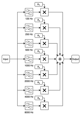
FREQUENCY SPECIFIC AMPLIFICATIONThose who are hard of hearing often find certain frequency ranges harder to hear than others. Frequency specific amplification can be used to amplify the percieved quieter frequencies. This can be achieved using bandpass filters. Different frequency bands can be isolated using a bandpass filter and can then be amplified depending on the patient's audiogram. All the bands are then summed together resulting in audio with some frequencies that are much louder than others to help combat the loss of hearing at those frequencies. This can be implemented with digital filters. Multiband IIR equaliser simulations were conducted using Simulink and the "filterDesigner" function of MATLAB. Simulink's graphical interface allows for rapid filter designing and testing; the second-order sections can then be exported and converted into bi-quad filter coefficients. Each bandpass filter, with equal gain and when summed together, should produce a flat response. This can be done by specifying the correct bandpass filter parameters that create a filter where the frequency response crosses with neighbouring bandpass filters to produce a flat overall response when summed together.
|
|
|
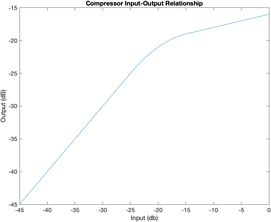
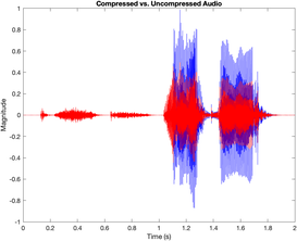
DYNAMIC RANGE COMPRESSIONPeople who are hard of hearing also suffer from a reduced dynamic range (difference between the hearing threshold and when sound is uncomfortably loud) and this presents a problem during noisy situations. An audio compressor reduces the dynamic range of audio making quiet parts and loud parts similar in their amplitude. Compressor operation is dependent on setting a compression threshold (often called the knee-point). Below this threshold, a compressor has a constant gain. Above it, the compressor "compresses" the audio by attenuating the input by an amount dependent on the compression ratio. The compression ratio is the ratio between the increase in input amplitude for a given increase in output amplitude. The transitions at the threshold need to be smooth. The attack time and release time parameters define the rate at which compression is applied. This “smooths” out the transition. Additionally, the “hardness” of the knee-point is a measure of how abrupt the transition at the threshold is. A “soft” knee has a smooth response and blends the two together, and a “hard” knee is an immediate transition. It is desirable to make the transition unnoticeable for the user.
|
FILTERS
Filters are often the simplest method of removing unwanted signals from audio. There are two main types of digital filters that can be implemented: Finite Impulse Response (FIR) and Infinite Impulse Response (IIR). Both are explained below.
FIR FiltersFIR filters do not rely on any feedback, so are inherently stable. Convolving the input signal with the designed impulse response filters the input signal. In more simple terms, the output sample is equal to a weighted sum of the current input sample and a finite number of previous input samples (length equal to the length of the filter). The value of the weights (often referred to as the impulse response) change the filtering properties of the FIR filter.
Designing the filter involves setting the weights. Because it does not rely on feedback, lots of coefficients (and therefore calculations) are required to produce a filter similar to an equivalent IIR Filter. This often makes them less efficient, but special DSP hardware can speed it up (Oshana, 2012). FIR filters are capable of having an arbitrary response, unlike IIR filters, which is beneficial in some applications. 
|
IIR FiltersIIR filters rely on feedback so have far fewer coefficients (when compared to an equivalent FIR filter), which significantly reduces processing time and latency (because each sample takes less time to pass through the filter). However, designing an IIR filter is more complex, and the phase response is ruined. The general procedure for IIR filter design is to start with a prototype analogue filter and convert it to an IIR filter. Computer software makes this design and conversion easy; however, selection of a prototype filter is required (Oshana, 2012). The properties of the selected prototype are retained after conversion, so selection is very important. The bi-quad filter is a 2nd order IIR filter and the figure below shows its block diagram. Higher orders can be obtained by cascading one bi-quad filter after the other.
|
BEAMFORMING
Filters cannot differentiate noise from speech when the frequency range of background noise overlaps with frequency range of speech. Alternatively, spatial filtering can yield better results. Spatial filtering is the isolation of speech from noise when they are physically separated in space. An example situation would be in a noisy restaurant with lots of people talking. Beamforming is a spatial filtering technique which uses an array of microphones.
Broadside Array
|
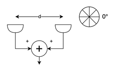
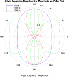
The broadside array method involves summing the microphone signals together to constructively or destructively interfere them.
In a two-microphone setup, the signal from audio sources at angles of 90°/270° are equidistant from each microphone and will reach each microphone at the same time. Summing them constructively interferes the two signals. At 0°/180° destructive interference can occur but only at certain frequencies which are dependent on the separation of the microphones. The resulting beamforming pattern is very frequency dependent; this is referred to as aliasing. It is better to have a consistent (for a wide range of frequencies) beamforming pattern, and broadside array beamforming cannot offer this. Furthermore, it captures audio from two opposite directions (90° and 270°) rather than a single direction further reducing its utility with speech audio. The frequency response at 90°/270° is ideal because it is consistent for all frequencies, but at 0° it changes. Overall, it is only effective if you wish to isolate a specific frequency. End-fire array beamforming addresses all these issues. |
|
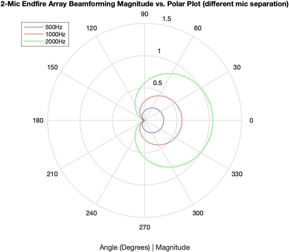
Endfire Array
|
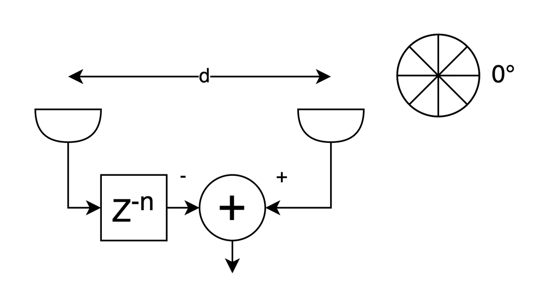
The simplest setup has two microphones. One microphone has its signal delayed by a number of samples equivalent to the time (in samples) it takes for sound to move the distance, ‘d’, between the microphones. The delayed audio is then subtracted from the other microphone (which has not had its samples delayed).
End-fire array beamforming captures audio from a single direction and the amount of attenuation at 180° is (in theory) infinite. Similarly to broadside array beamforming, aliasing does occur. This makes it suitable for audio. For a more detailed explanation, read the full dissertation below. The distance between the microphones is key and, if altered whilst keeping the same sample delay, the beamforming pattern is altered. The frequency response (at 0°) produces a comb filter attenuating lower frequencies (where speech commonly resides). This is bad and needs to be corrected. To recover lower frequencies from the beamformed audio, an FIR lowpass filter can be applied isolating lower frequencies. These are then amplified and summed with the original beamformed audio boosting lower frequencies. Setting the FIR filter and amplification is essential to ensure a resulting flat response. |
|
MICROCONTROLLER IMPLEMENTATION
|
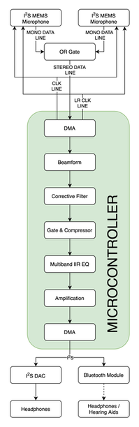
DSP relies on computing lots of calculations quickly. The STM32H743ZITx designed by STMicroelectronics uses an ARM Cortex M7 processor with up to a 480MHz clock speed and floating-point unit (FPU) to speed up DSP calculations. It also has the required peripherals including 3x I2S busses, 16-bit ADCs and has Direct Memory Access (DMA) functionality which will reduce the load on the processor. It also includes special hardware and operation codes for DSP.
Some modern hearing aids include Bluetooth functionality and can act as wireless headphones. Using Bluetooth source chips like the Microchip BM83 or Qualcom CSRA64215, the concept device can have Bluetooth. Both chips use the A2DP audio codec. This is the most widely accepted audio codec for Bluetooth classic audio; it has a standard sample rate of 44100Hz. The device will output audio via I2S because both Bluetooth chips use it for audio input. An I2S DAC will be used in place of the Bluetooth chips which can be swapped out when the chips are back in stock. The I2S MEMS microphones were setup with DMA which allows the clock signals and data reception to run in parallel with the CPU. The DMA fills a circular buffer of length 256 samples and half complete and complete call-back functions are triggered as the buffer is being filled. This creates a “tick-tock” system where half the buffer is processed whilst the other half is written to. It adds at least 2.9ms of latency to the audio (in addition with other latencies). The processing for each call-back must be completed before the other is triggered so, during development, the time of each call back was measured to ensure this did not happen. |
|
CONCLUSION
Although not a complete success, the project has achieved most of the objectives.
This project has shown that a device, like the concept laid out in this document, is possible, cost effective and most importantly could benefit the 10 million people in the UK suffering from hearing loss. It lays out a clear path for future developments in assisted listening accessories, the possible techniques that could be used and limitations of current technology at implementing complex DSP techniques.
- Beamforming exceeded the objectives, having a 12dB attenuation at 180° and 90°/270° with only a single direction of audio being captured. Lower frequencies were successfully restored with the 200Hz only being 3.7dB lower than the 4000Hz frequency and the microphone separation was 23mm, less than the 50mm for the device to be pocketable.
- The PPM was able to reach 99% of the desired level in 21 samples (467μs), well below the maximum of 2ms. Both the compressor and noise gate are configurable meeting the objectives.
- The gate’s hysteresis and fade-out time and the compressors knee, threshold and compression ratio are all customisable, as desired. It all worked as expected.
- The multiband equaliser met most of the objectives and successfully amplifies each frequency band for each ear based on a person’s audiogram. However, some of the bandpass filters produced peaks and troughs when combined together. But overall the implementation works and the filters can be modified.
- The device’s latency was acceptable, with the total latency measured as 14.5ms without taking into account the added (and significant) latency of Bluetooth. If this was to increase the latency above 20ms the gates FIFO buffer could be removed saving a further 6.8ms.
- Finally, the implementation and hardware choices meets all the objectives set out.
This project has shown that a device, like the concept laid out in this document, is possible, cost effective and most importantly could benefit the 10 million people in the UK suffering from hearing loss. It lays out a clear path for future developments in assisted listening accessories, the possible techniques that could be used and limitations of current technology at implementing complex DSP techniques.
