OVERVIEW
This is the original project that I started in 2017. I made lots of errors and was naive about how big of a challenge it would be. When I was 17, my programming skills were poor, and I did not do enough research before designing my drone. Below is an explanation of this original design and code and a critical evaluation of my work. Eventually, I did manage to get the drone to fly but it was not stable. I believe that now I have gained enough knowledge to complete the project. Click the button below to see the current design.
ORIGINAL DESIGN: PROS AND CONS
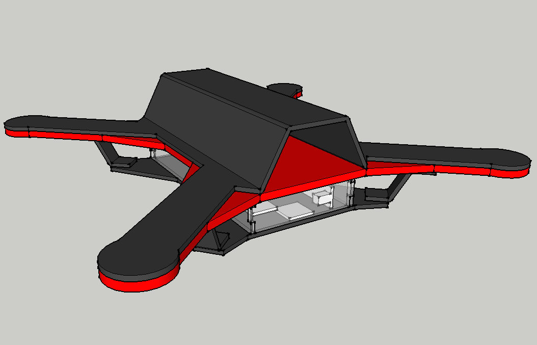
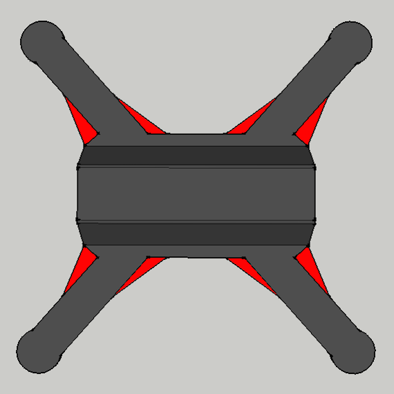
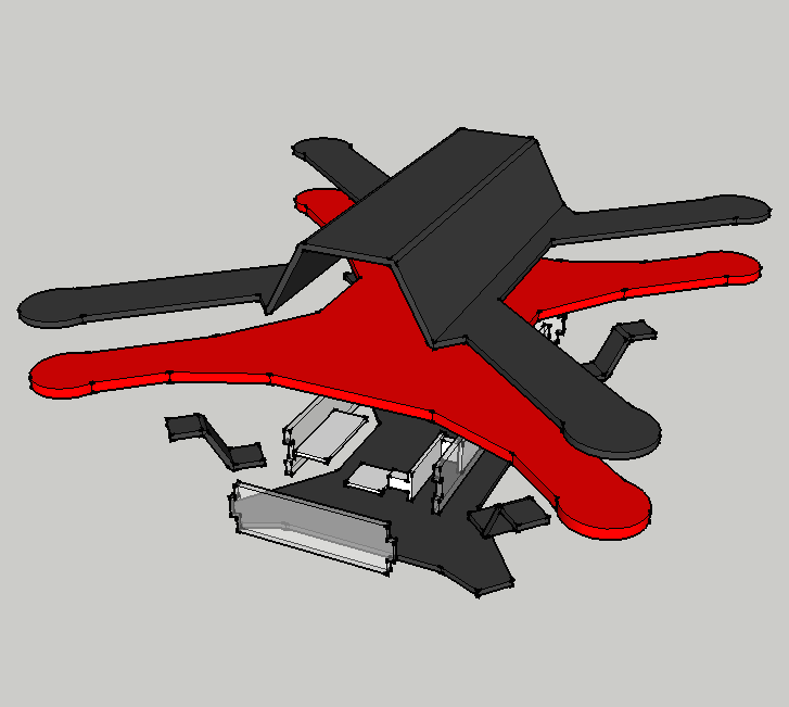
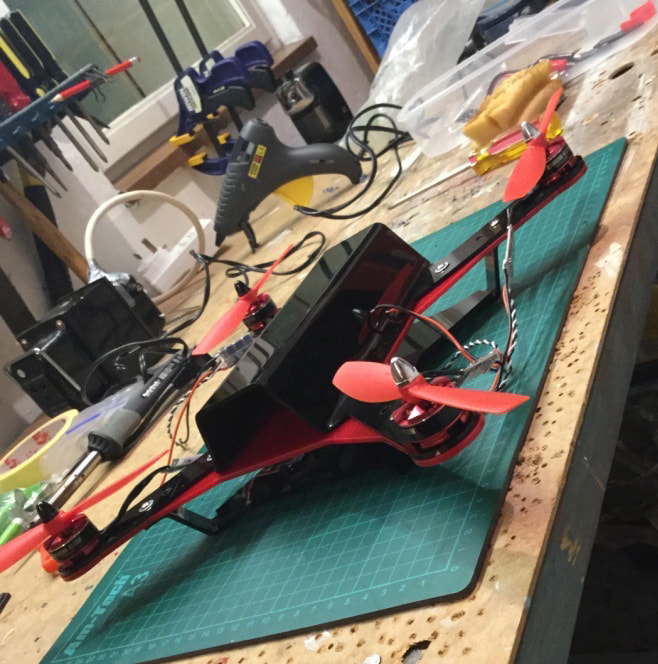
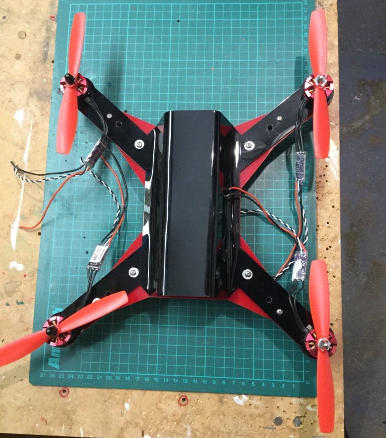
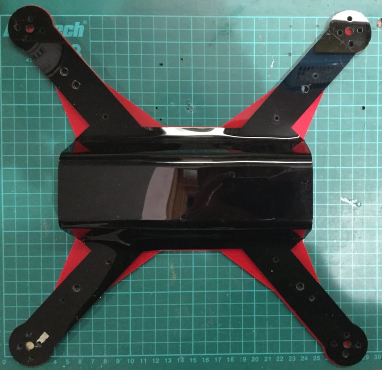
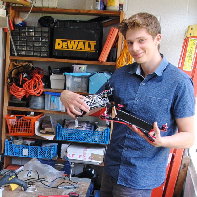
The original drone design was a two-level design. The underside contained all the electronic components and sensors to control the drone's flight, and the topside contained a large space for the battery. The design comprised of 11 parts, all made from acrylic, which were laser cut and line bent into the correct shape. All the parts were held together using screws and/or glue. The shape of the drone was made to be strong and lightweight and to reduce drag. The position of the motors is in a square shape, and the body is longer than it is wide so that the battery could fit.
Pros:
The benefit of this design was that I was able to make it at home with my current set of tools. It also looked good and I intend to keep the design aesthetic on my next iteration but completely change the materials.
Cons:
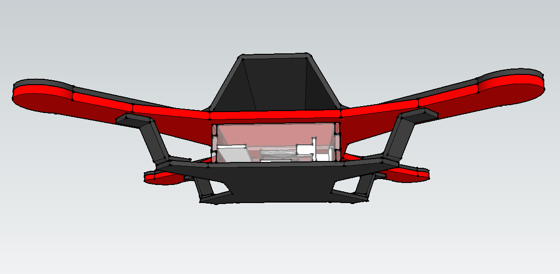
I had not completely thought through the weight distribution of the drone. The battery raised the centre of gravity above the level of the motors which caused it to force the drone to roll over. The drone would have to compensate for this. If the battery was held under the level of the motors it would act like a pendulum and would improve the drone stability. The choice of using acrylic was a big mistake. It is easy to laser cut and can be bent easily but cannot take an impact as well as other materials.
Pros:
The benefit of this design was that I was able to make it at home with my current set of tools. It also looked good and I intend to keep the design aesthetic on my next iteration but completely change the materials.
Cons:
I had not completely thought through the weight distribution of the drone. The battery raised the centre of gravity above the level of the motors which caused it to force the drone to roll over. The drone would have to compensate for this. If the battery was held under the level of the motors it would act like a pendulum and would improve the drone stability. The choice of using acrylic was a big mistake. It is easy to laser cut and can be bent easily but cannot take an impact as well as other materials.
BATTERY
Weight was an important consideration. To extend flight time, the drone needed to consume as little energy as possible during flight, and the heavier it is, the more energy it will consume. To have a longer flight time, a high-capacity battery was necessary to deliver energy for longer but higher capacity batteries are heavier. I chose a 4200mAh battery that weighed 342g because I believed this was a good compromise. This is the heaviest part of the drone.
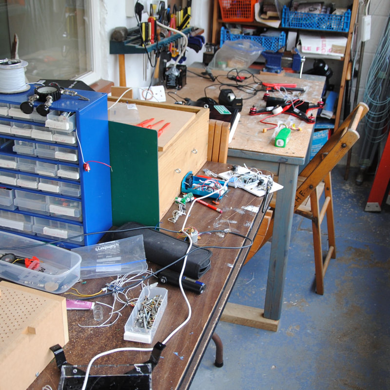
ORIGINAL BUILD
I laser cut the acrylic parts at school using the laser cutter and used a line bender to shape it to the correct shape. I then used a hand drill to drill holes into the parts so that screws could be fitted through and join the parts together. This was challenging, as the acrylic is 3mm thick and brittle. I had to use a higher RPM on the drill and took it slow; this prevented the plastic from cracking.
The brittle nature of acrylic should have been a clear warning sign that I should have re-thought my design.
The brittle nature of acrylic should have been a clear warning sign that I should have re-thought my design.
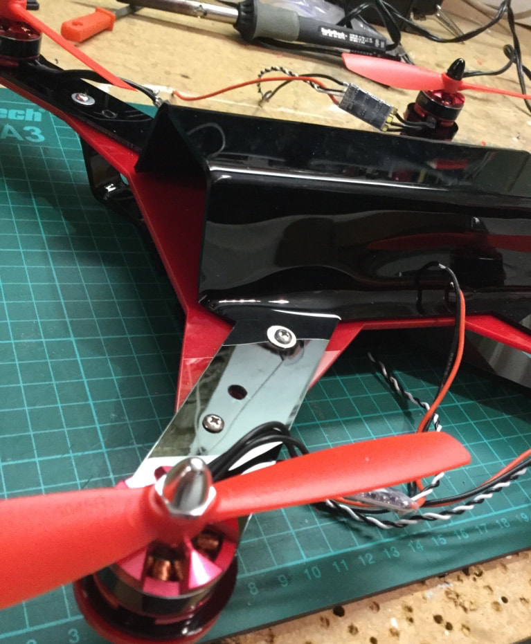
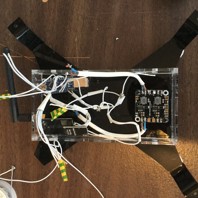
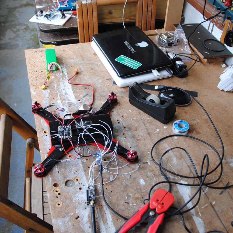
The drone uses an Arduino Nano microcontroller, an MPU6050 accelerometer and gyroscope, an RF24 2.4Ghz transceiver (with a range of 0.5km), four ESCs (Electronic Speed Controllers) and a power distribution board. These parts were soldered together within the drone's underbody. I believe that the electronic parts that I chose are suitable and I currently do not believe that I made a mistake with my choices.
ORIGINAL PROGRAMMING
The drone uses an Arduino nano microcontroller programmed in Arduino IDE using C++. The Arduino nano is the brains of the drone.
The RF24 transceiver sends data over a 2.4GHz radio band and allows the remote and the drone to communicate. The remote also has an Arduino onboard and two thumbsticks as input to control the drone. The RF24 has a long enough range and high enough rate of data transfer to be used in this application.
The MPU6050 is an accelerator and gyroscope board and communicates over an I2C bus giving data on the angle and movement of the drone.
Here is the general overview of how the drone works:
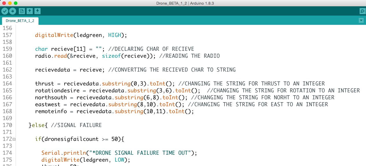
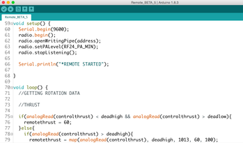
The Arduino onboard receives data from the RF24 transceiver module containing information on the amount of thrust required, the amount of yaw rotation and the direction the drone needs to move. The MPU6050 (accelerometer and gyroscope module) connected to the Arduino (via an I2C bus) outputs data on the angle and the rate of change of the angle of the drone using the accelerometer and gyroscope respectively, and these are together used to calculate a value for the angle of the drone relative to the horizon. Using PID (proportional, integral and differential) calculations, the drone can calculate the motor speeds that are required to correct and balance the drone. At this point, the data from the RF24 transceiver is incorporated so that the drone is able to balance at an angle to the horizon; this is required so that the drone can move in a given direction. The information from the PID calculations about the motor speeds are converted into four PWM (Pulse Width Modulation) signals that are each sent to the individual ESCs (Electronic Speed Controllers) for each motor. A PWM signal is a periodic electronic pulse that is sent to the ESC. The time that the pulse is on vs the time it is off gives information on the speed that the motors need to rotate.
The RF24 transceiver sends data over a 2.4GHz radio band and allows the remote and the drone to communicate. The remote also has an Arduino onboard and two thumbsticks as input to control the drone. The RF24 has a long enough range and high enough rate of data transfer to be used in this application.
The MPU6050 is an accelerator and gyroscope board and communicates over an I2C bus giving data on the angle and movement of the drone.
Here is the general overview of how the drone works:
The Arduino onboard receives data from the RF24 transceiver module containing information on the amount of thrust required, the amount of yaw rotation and the direction the drone needs to move. The MPU6050 (accelerometer and gyroscope module) connected to the Arduino (via an I2C bus) outputs data on the angle and the rate of change of the angle of the drone using the accelerometer and gyroscope respectively, and these are together used to calculate a value for the angle of the drone relative to the horizon. Using PID (proportional, integral and differential) calculations, the drone can calculate the motor speeds that are required to correct and balance the drone. At this point, the data from the RF24 transceiver is incorporated so that the drone is able to balance at an angle to the horizon; this is required so that the drone can move in a given direction. The information from the PID calculations about the motor speeds are converted into four PWM (Pulse Width Modulation) signals that are each sent to the individual ESCs (Electronic Speed Controllers) for each motor. A PWM signal is a periodic electronic pulse that is sent to the ESC. The time that the pulse is on vs the time it is off gives information on the speed that the motors need to rotate.
|
|
My coding skills at the time that I started this project were poor and as such the code is written inefficiently. It needs to be compartmentalised into functions; I was un-aware that this was possible at the time.
To my credit, the format of variables was constant and the layout of the code is clear.
To my credit, the format of variables was constant and the layout of the code is clear.
WHAT I LEARNT AND FUTURE IMPROVMEENTS
Below is a list of improvements I would need to make to complete this project:
- Source a new material for the body of the drone.
- The choice of acrylic was a bad idea because of its material properties.
- During a test flight, the Arduino running the flight control programme lost power, and the drone fell out of the sky, shattering the body of the drone beyond repair. Until I remake the drone, I cannot test fly it.
- I think ABS will be a better material and opens up the ability to 3D print the parts, but I will need to research more before I decide.
- Find a way to make the drone
- I think the best way to make it will be to 3D print the drone into parts that can easily be assembled, however this restricts the possible materials that I will be able to use.
- I wish to construct it from multiple parts so that, if a piece needs to be changed or breaks, it can be replaced with ease.
- Re-design the body of the drone
- So it can be made in the new method I decide to use.
- So it can be 3D printed etc.
- Re-design so that it can be modular.
- Re-design so that the battery sits below the drone not above it.
- So it can be made in the new method I decide to use.
- Find a better way to test the code.
- I need to design a better testing environment so I can develop the code. The main reasons to do this are:
- The weather is often bad, and I need to be able to test inside
- I also want to be able to limit the different ‘variables’. This can be done by restricting the possible motion so that I am able focus on one aspect.
- Developing the drone by flying it and then changing the code and repeating does not allow me to focus on the changes that I am making.
- I think I will build a contraption that is similar to a ‘seesaw’ that can rotate. On each end of the ‘see saw’ will be a motor and propeller.
- I need to design a better testing environment so I can develop the code. The main reasons to do this are:
- Research more
- Learn more about PID systems. I used PID when I originally made the drone, but I want to be able to refine it so that flight is steadier.
- I want to look into new microcontrollers that may be more capable than the Arduino Nano I was using.
TEST FLIGHT
|
With all my mistakes considered, I was still able to make the drone fly and, on the right, you can see a video of some of the test flights.
Having to test outside caused the drone to be affected by wind. I also did not have yaw control so it would rotate randomly. I will need to tweak the drone code and certain parameters to produce more reliable and stable flight. |
Two axis stabilisation and hover tests.
|
